Energy of vortex motion of a liquid and possibilities of its practical use
Currently, the world is actively searching for new alternative energy sources that do not harm the environment. In the process of this search, two main directions of obtaining such energy were formed.
 The founder of the first direction is M. Tesla, with his idea of obtaining energy from the surrounding space. About his ideas, in particular his patented transformer, permanent magnet motor, etc. there is an active discussion.
The founder of the second direction is rightly considered to be W. Schauberger, with the theory of water energy developed by him. Many authors write about fruitless attempts to put into practice the theory of W. Schauberger, as well as to make a vortex motor.
One of the sites devoted to the study of vortex energy chose as its epigraph the quote "PRIMARY ENERGY IS A CAUSE, SECONDARY FORM IS A CONSEQUENCE". This emphasizes the fact that humanity is not yet clear the fundamental principle that explains the processes occurring in vortex apparatus.
In the proposed article, we want to consider the practical application of the vortex motion of a fluid.
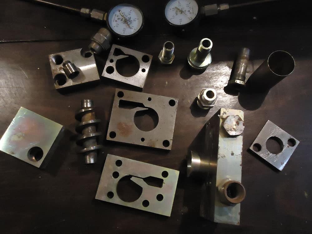
To explain the mechanism of formation of additional energy in the devices realizing vortex motion of liquid, we will consider the device which scheme is resulted in fig. 1 and we will name its hydrocyclone (GC)
The hydrocyclone consists of a housing 1 with a conical central channel, which houses a conical activator made in the form of an auger, the screw channel of which narrows, and two covers - the inlet 3 and the outlet 4. (Fig.1)
Suppose that a liquid with a flow rate of Q passes through GC.
Consider the energy equation for sections 2a -2a of the activator - at the exit of the tapering screw channel and 2-2 - at the entrance to the channel (a) (Fig. 1). The pressure in these sections is the same and equal to p2. In section 2a -2a, the flow moves along the helical channel in plane parallel, and the energy per unit mass of the flow W2a is determined from the expression:
W2a= Eo+ p2/ρ + Q2/ ( 2f2),
where: Eo is the internal energy per unit mass of the flow,
f is the cross-sectional area of the tapering helical channel at the outlet of the activator,
ρ is the density of the working fluid,
Q is the consumption of working fluid.
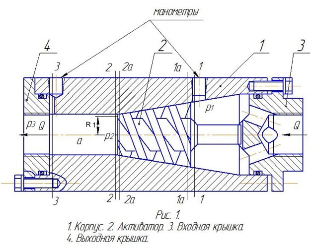
- Housing
- Activator
- Entrance cover
- Output cover manometers
In section 2-2, the flow simultaneously moves parallel to the axis with the speed Q / F2 (because the principle of continuity of the flow) and rotates around the axis with an angular velocity ω = Q / fR.
The energy per unit mass of the flow is determined from the expression:

where: E1 is the internal energy per unit mass of the flow in section 2-2,
F2 is the cross-sectional area of the channel (a),
R is the radius of the helical channel on the activator cone (Fig.1),

- energy per unit mass of flow, resulting from the action of centrifugal forces of portable vortex motion. Since the inflow of energy from the outside is absent W2a = W2.
 (1)
(1)
This equation takes into account that part of the hydraulic energy of the flow (Q2 / 2 f2) at the entrance to the channel (a) passed into the internal energy (sudden expansion of the flow, ie the separation of the flow from the walls).
Given that F2 >> f, ie Q2 / (2F22) = 0, from equation (1) it follows:
Q2 / (2f2) = E0 - E1,
that is, part of the internal energy of the flow is converted into hydraulic energy of portable motion, which at the output of the GC is converted into potential energy of pressure.
Consider the Bernoulli equation for sections 1-1; 2a -2a; 2-2 and 3-3. Taking into account that in section 3-3 the flow has a plane-parallel motion (if necessary, in the channel (a) can be installed flow rectifier), we obtain the formula:
p1 / ρ = p3 / ρ - (1 - λ L / d) Q2 / (2f 2) (2),
where: λ is the coefficient of hydraulic resistance,
L is the length of the tapering helical channel,
d is the average hydraulic diameter of the cross sections of the tapering helical channel,
p1 - pressure at the inlet to the shopping center,
p3 - outlet pressure.
Note that this expression will be true in the absence of cavitation, ie at p2> 0, or p3> Q2 / f2 (absolute pressure).
From equation (2) it is seen that the flow power at the exit of the GC is greater than at the entrance to it due to part of the internal energy of the working fluid, and the magnitude of this difference is determined by the geometric dimensions of the activator L; d; f and the value of the flow rate of the working medium The difference between the input and output hydraulic power δN:
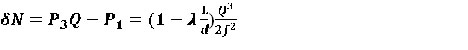
δN depends on Q and f and can reach any value.
Schauberger's nozzles and implosion machine (including the "home generator"), Klem's vortex motor, and Potapov's heat generators work according to the principle described above.
Our creative group has been studying this area for more than 10 years. During this time we have developed a method of calculating turbines on the above principle for any capacity and made a design study of a turbine with a capacity of 20 kW, experimental samples of outboard motors (water cannons) with a traction force of 20 and 50 kg operating on seawater.
In addition, we have developed devices that implement a vortex that reproduces itself, developed a method of calculating them and on this principle developed:
- Heating boiler with a thermal capacity of 45 kW;
- Engine with a capacity of 2.7 ... 4.5 kW.
To date, we have carried out work on the practical use of the energy of the vortex motion of a liquid as exploratory, based solely on our own enthusiasm. However, the accumulated experience allows to carry out an exit on manufacturing of prototypes. Our group is looking for an investor who is ready on mutually beneficial terms to finance further work, production of equipment samples, and their testing.
In case of interest in this information, please write:
E - mail: yushtexcenter@yandex.ru
A.A. Bulavin engineer, O.B. Leszczynski engineer.